
A 0.30 mm oil hole can fail because of five micrometres of runout, a blocked coolant passage, an incorrect feed calculation, or a burr that inspection never detects. By the end, you will be able to separate tool, alignment, coolant, programming and measurement faults, then decide when micro drilling is the wrong process.
Key takeaways
- Confirm depth, diameter, material and hole type before changing machine settings.
- Control chip evacuation with suitable coolant flow and conservative peck cycles.
- Match drill geometry and workholding to the entry face and breakthrough conditions.
- Inspect hole size, position and cleanliness before approving production equipment.
Define the Hole Before You Diagnose the Machine
A 0.30 mm oil hole is a viable CNC micro drilling job when its depth, tolerance, entry face and material suit the drill. Check the depth-to-diameter ratio, hardness, abrasiveness, cross-hole intersections, and whether the hole is blind or through.
An angled face, interrupted cut or deep passage can require a starter feature or a different process.
| Hole condition | Viability signal | Starting test |
|---|---|---|
| Diameter and depth | Solid carbide drill reaches the required depth without excessive slenderness | 15,000–30,000 rpm; feed 0.01–0.03 mm/rev |
| Material | Aluminium, mild steel and free-machining alloys cut more easily than hardened steel or abrasive cast iron | Use the toolmaker’s speed first; reduce speed for hard material |
| Depth-to-diameter ratio | Up to about 5×D is a practical initial trial; greater depths demand chip-control evidence | Peck 0.5–1×D, with no dwell at the bottom |
| Entry and exit | Flat entry and supported breakthrough reduce wandering and burrs | Spot or pilot only if the drill maker permits it |
| Coolant path | Through-tool oil reaches the cutting edge at the actual tool | Confirm flow at the drill, not only at the pump gauge |
Before blaming the small hole drilling machine, measure tool runout at the drill; 5 µm is already 1.7% of a 0.30 mm diameter. Warm the spindle, stabilise coolant temperature, then repeat the test because thermal drift can imitate location or depth errors. Validate new and reground drills separately.
Trace Breakage, Wandering and Size Errors in Order
Find the fault in order: tool condition, runout, workholding, coolant delivery, cutting data, then CNC offsets. Changing several variables at once hides the cause. Use this order when troubleshooting micro drilling machine oil hole drilling for problems:
1. Inspect the drill under magnification. A chipped margin points to overload or rubbing; a packed flute points to chip evacuation. Check the entry and exit for burrs before blaming diameter.
2. Measure runout at the mounted drill, not only at the empty spindle taper. A 5 µm radial error equals 1.7% of a 0.30 mm drill diameter, loading one flute harder and causing wandering, oversize holes or breakage.
3. Clamp the workpiece and verify its support at entry and exit. Movement creates location error, taper and inconsistent depth. Replace a conventional center-drill start if its chisel or countersink leaves an oversized, hardened transition.
4. Confirm that cutting oil or coolant reaches the cutting zone. Chip-packed deep holes need a process change, not endlessly aggressive pecks; single-lip or gun drilling may be more stable beyond a two-flute drill’s practical depth.
5. Recalculate feed per revolution after every spindle-speed change. Reducing rpm without reducing feed raises chip load and can break an apparently sound drill.
6. Compare cold-start and thermally stabilised holes. Spindle growth, coolant temperature and delayed tool measurement produce apparent location, diameter and depth errors.
7. Check tool length, work offsets, drilling depth, peck retract and dwell in the CNC program. Measure with air gauging, optics or a calibrated pin; burrs and excessive contact can make a correct hole appear undersized. These checks isolate micro drilling machine problems before you alter the machine.
Use Coolant and Peck Cycles to Control Chips
Chip packing, not inadequate spindle power, is often the first cause of micro-drill failure. Trapped chips block coolant from reaching the cutting edge, drive torque sharply higher and snap the drill during withdrawal or re-entry. The same debris can remain in the finished oil passage and restrict flow.
For oil hole drilling machine troubleshooting, verify coolant at the tool, not only at the pump gauge. Through-tool coolant usually reaches a small hole more effectively than an external jet, but blocked filters, rotary-union restrictions and clogged tool passages can reduce actual flow.
Check the delivery path at the spindle, then inspect the hole for packed chips after cutting.
Set peck depth from the chips you observe, the material and the hole depth-to-diameter ratio. An arbitrarily short peck creates repeated re-entry shocks and can damage the margin more than a longer, chip-breaking peck.
Use a partial retract when coolant clears the chips without removing the drill from the hole; retract to the clearance plane when chips pack or coolant cannot flush the cutting zone.
A standard two-flute micro drill becomes less tolerant as depth increases. If repeated full withdrawals and aggressive pecks still leave blocked passages, compare a gun-drilling or single-lip process rather than forcing a twist-drilling cycle beyond its stable range. Check hole cleanliness and chip evacuation before blaming drill diameter or spindle speed.
Match the Tool and Workholding to the Entry and Exit
An angled face can push a micro-drill sideways before its lips cut. Make a flat spotface, use a short solid-carbide drill, and hold the part against a rigid fixture rather than relying on vise pressure.
| Condition | Drill and starter | Support and breakthrough method |
|---|---|---|
| Angled entry | Use a split-point or four-facet drill; spotface the entry instead of using a conventional center drill | Clamp close to the hole and reduce entry feed until both lips are cutting |
| Deep oil hole | Use the shortest suitable carbide drill, a margin that suits the material, and through-tool coolant where available | Add a guide bush or close support; choose pecks from chip formation, not an arbitrary distance |
| Thin exit wall | Use a sharp drill with controlled edge preparation and reduce feed as the web reaches the exit | Fit a sacrificial backing plate or leave a small exit web for a second operation |
| Cross-hole intersection | Use a drill suited to interrupted cutting and check the intersection location in the program | Support the intersecting wall; slow feed through the opening to limit breakout and edge chipping |
A conventional center drill can leave a hardened, oversized countersink that lets the final drill wander. Treat the starter diameter, included angle and oil-hole diameter as one geometry.
On a cnc micro drilling operation, verify runout at the drill tip and clamp the workpiece so it cannot lift during breakthrough. A small hole drilling machine also needs thermal stability: spindle warm-up and coolant temperature changes can shift the apparent entry and exit position.
Prove the Result Before Choosing a Production System
Do not choose a production system until a controlled trial proves the hole, not just the drill. Measure diameter with air gauging, optical measurement or calibrated pins after removing entry and exit burrs; a forced pin can hide an undersize hole or enlarge a soft edge.
- Check straightness with optical inspection, a certified gauge method or sectioned samples when the depth-to-diameter ratio makes deflection likely.
- Verify depth against a datum using a depth probe or cross-section, and compare cold-start parts with parts cut after spindle warm-up and coolant-temperature stabilisation.
- Flush every passage, then confirm pressure or flow. Use borescope inspection where practical, or a validated wash-and-filtration test, because a correctly sized hole can still contain a compacted chip or abrasive residue.
- Record spindle load, acoustic events, hole size, burr height and breakthrough behaviour across a defined tool-life trial. Qualify reground drills separately by checking runout, straightness, size and life; a changed point angle or web can shift cutting forces.
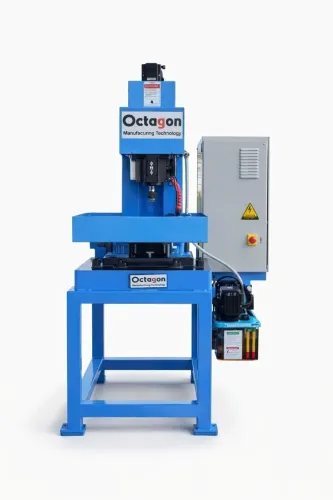
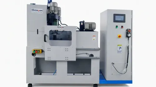
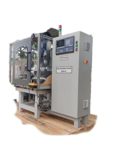
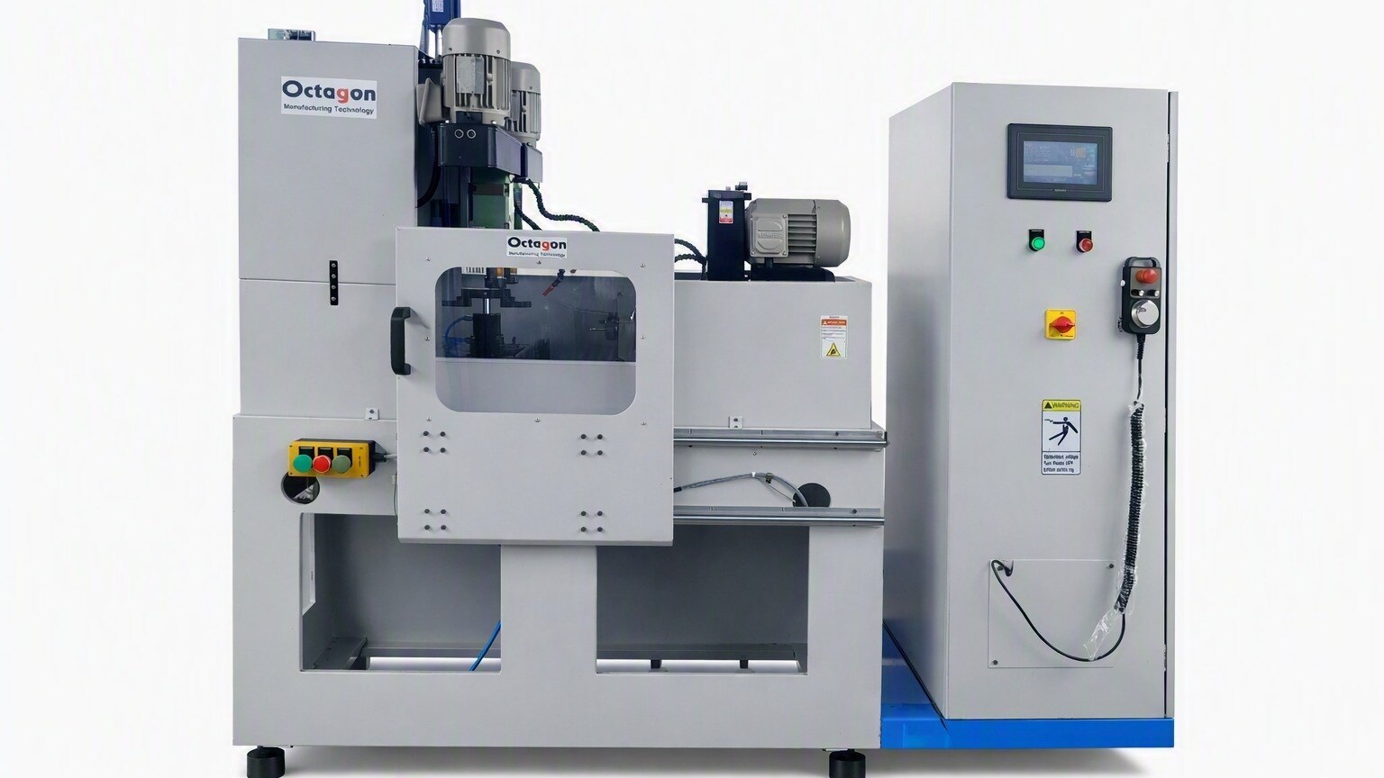
This evidence turns oil hole drilling machine troubleshooting from guesswork into a process decision. Give OCTAGON MANUFACTURING TECHONOLOGY this feature sheet when asking whether a dedicated CNC layout fits your volume and cycle time.
| Option | Compare when | Main reason |
|---|---|---|
| Micro drilling | Short or moderate holes | Lowest process change |
| Gun drilling | Deep, straight passages | Better chip evacuation |
| EDM | Hard material or difficult geometry | No cutting force |
| Laser processing | Tiny openings or thin sections | Fast non-contact entry |
| Dedicated CNC machine | Repeated parts and multiple holes | Stable automation and inspection pairing |
Related product
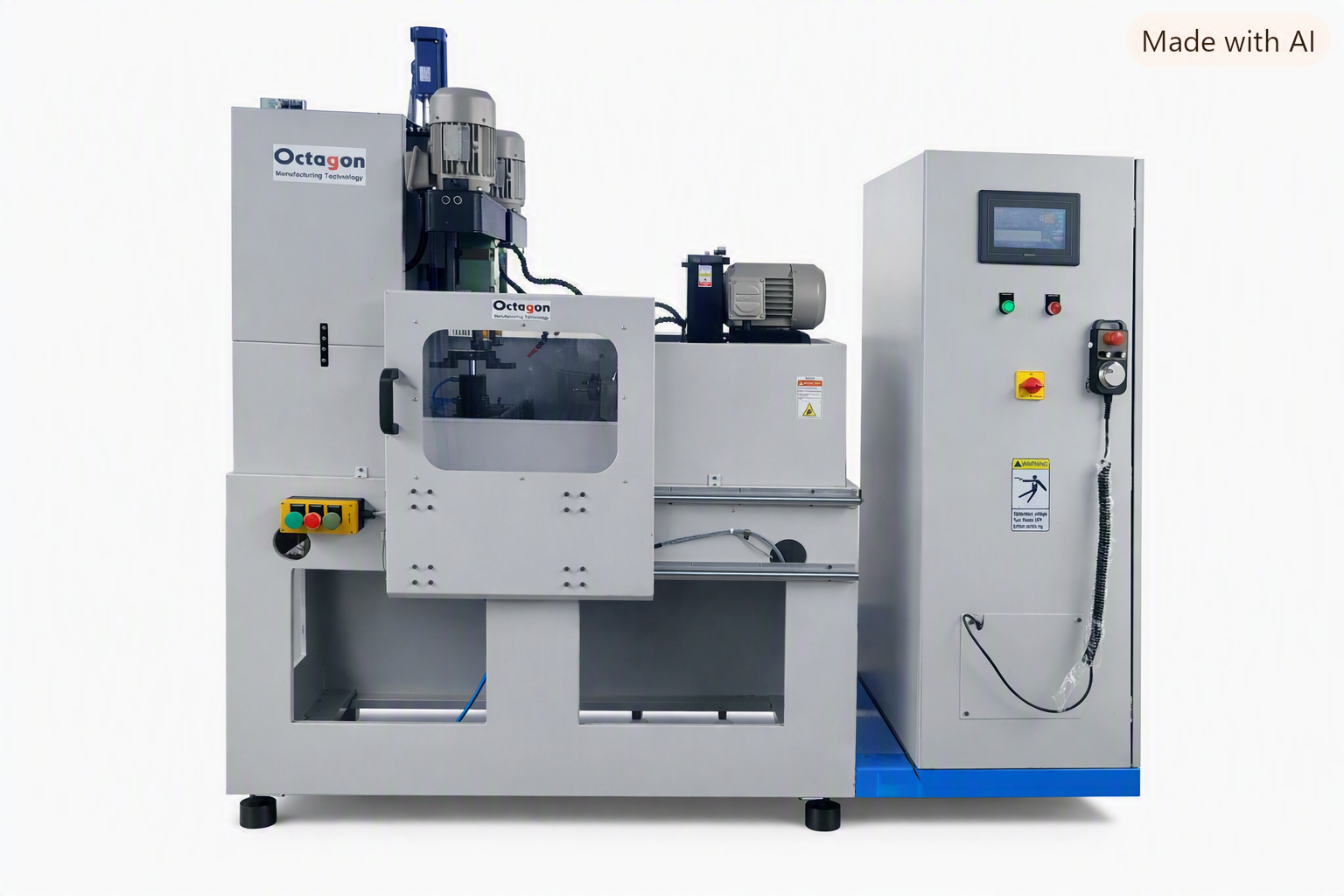 | cnc High-productivity 4-spindle CNC oil hole drilling SPM designed for accurate, repeatable and high-volume drilling operations. View product → |
Frequently asked questions
What should you define before diagnosing CNC micro drilling problems?
Record the hole diameter, depth-to-diameter ratio, tolerance, material hardness, abrasiveness, entry face, and whether the hole is blind or through.
How do you trace drill breakage, wandering and hole-size errors?
Check the tool, spindle runout, workholding, entry surface, cutting data, chip evacuation and inspection results in that order.
How do coolant and peck cycles prevent oil hole drilling problems?
Use coolant that reaches the cutting zone and set peck cycles to clear chips before they pack, rub or break the drill.
How do you prove a micro drilling machine will produce acceptable holes?
Run representative parts and verify diameter, position, depth, breakthrough, burrs and cleanliness with suitable inspection methods before production selection.