
A timing hole establishes where a component is indexed; an oil hole establishes how lubricant reaches a working surface. Identify the hole’s function, geometry, accuracy risk and production volume, then match the part to a dedicated machine, flexible CNC platform or another process.
Key takeaways
- Define the hole’s function before selecting drilling equipment.
- Control timing-hole angle from a datum, keyway, or mating feature.
- Inspect oil passages for burrs, blockage, depth, and intersection quality.
- Specify spindle, tooling, fixturing, inspection, and cycle-time requirements together.
Start with the hole’s function, not the machine name
A timing hole establishes a positional or angular reference; an oil hole creates a passage for lubricant. A timing hole can phase a pulley, sprocket, gear or camshaft-related component against a keyway, mark or mating feature. An oil hole carries lubricant from a source to a bearing, journal, gallery or intersecting passage.
| Function | Timing hole | Oil hole |
|---|---|---|
| Purpose | Sets angular clocking or positional reference | Forms a lubrication route |
| Typical features | Reference holes in gears, pulleys, sprockets and camshaft parts | Radial, axial or angled holes in shafts, bushes, connecting rods and housings |
| Main acceptance criteria | True position, clocking angle, diameter and repeatability from functional datums | Diameter, depth, intersection, passage continuity, burr condition and cleanliness |
| Main failure | Correct diameter but wrong phase relative to a keyway or bearing seat | Chips, burrs or misalignment restrict lubricant flow |
The comparison timing hole drilling machine versus oil hole drilling machine describes an application, not a universal machine category. One CNC platform can produce both, but the controls differ: timing work prioritises datum-based location and orientation, while oil-hole work prioritises reach, chip evacuation and a clean passage.
A three-axis setup suits a fixed, perpendicular pattern; angular timing holes need controlled part orientation, and intersecting oil passages need drilling and flushing plans. Locating a casting or forging only on rough surfaces can transfer its variation into either hole, so use machined functional datums when the design provides them.
When a timing hole needs angular control
A timing hole needs angular control when its clocking relative to a keyway, gear tooth, bearing seat, shaft flat, or timing mark affects assembly or operation. A hole can meet its diameter and depth targets yet fail if it is rotated from the functional datum.
A timing hole drilling machine therefore needs workholding that fixes both location and orientation.
| Option | Workholding and motion | When it applies |
|---|---|---|
| Fixed locating nest | Locates on machined faces, pilots, or a keyway; no rotary axis required | One hole pattern, one orientation, and drilling from a fixed face |
| Indexing spindle or angular chuck | Clamps the part and turns it to defined positions | Discrete clocking positions around a shaft, pulley, sprocket, or gear |
| CNC rotary axis | Rotates the component continuously while the tool approaches at programmed angles | Multiple holes at different angles, circumferential patterns, or angled entry faces |
Use functional machined datums whenever the design permits them. Locating a casting or forging only on rough external surfaces transfers its variation into the hole position and may shift the timing relationship.
Choose a dedicated locating nest when the component family and pattern stay stable; it reduces handling and cycle time. Choose an indexing spindle when the part must rotate between known stations. Choose a rotary axis when angular positions vary or several faces require access.
A machining centre remains the safer choice when parts, datums, or hole patterns change frequently.
Design the oil-hole process around passage quality
Oil holes fail as passages, not merely as dimensions: a drill can meet diameter and depth while a burr or chip blocks lubrication flow. Specify the passage from the oil source to the bearing, journal, gallery or cross-drilled hole, including every intersection and the direction of flow.
1. Define the drilling method from diameter, depth and material. Treat a depth-to-diameter ratio near 10:1 as a process boundary, not a guarantee that peck drilling will work. A long, small-diameter passage may need gun drilling, high-pressure coolant and guide pads; larger passages may suit BTA or ejector drilling.
An oil hole drilling machine is not automatically a deep-hole system.
2. Control chips before they reach an intersection. Set coolant pressure, flow, peck or chip-breaking cycles and tool withdrawal distances for the material and hole geometry. Capture chips during flushing; one fragment left in an internal gallery can restrict flow after assembly.
3. Remove burrs at entries, exits and cross-hole intersections. Specify the deburring tool, chamfer size and access direction, then verify that deburring has not enlarged the oil-feed opening or left a feather edge inside the passage.
4. Inspect passage function, not only hole size. Use gauges or CMM measurement for diameter, depth and location, then add borescope or visual inspection, flushing and chip capture. Run an air-flow or pressure-drop test at defined pressure when the hole feeds lubrication or connects internal galleries; record the result for each part.
Choose between dedicated drilling and flexible CNC equipment
Choose dedicated equipment when one component family runs at stable volume, hole locations and orientations rarely change, and loading or indexing dominates cycle time. Choose a machining centre when patterns, datums or part families change frequently; its flexibility outweighs the dedicated machine’s shorter cycle.
| Option | Choose it when | Reject it when |
|---|---|---|
| Dedicated timing-hole or oil-hole machine | High volume, fixed geometry, repeatable loading, and special indexing, angular drilling or simultaneous operations justify engineering cost | Product mix or datum schemes change often |
| Machining centre | You need multiple tools, changing hole patterns, complex datums or frequent design updates | A stable part spends most of its cycle on repetitive drilling and handling |
| Radial drill | Low volume, accessible surfaces and operator-led positioning are acceptable | You need controlled angular position, repeatability or automatic chip and coolant management |
| Gang drill | Several fixed holes can be drilled in one simple sequence | Hole orientations, depths or part variants require flexible CNC positioning |
| Manual fixture | Prototypes, repairs or short runs make automation uneconomic | Labour, loading variation or inspection risk threatens takt time |
| Outsourced operation | Demand is uncertain, equipment investment is unjustified or specialist deep-hole capability is unavailable | Transport, queue time, confidentiality or repeatability becomes costly |
A cnc oil hole drilling machine is not automatically a deep-hole machine. For long, small-diameter passages, specify gun drilling, high-pressure coolant and chip evacuation; use conventional peck drilling for shorter passages.
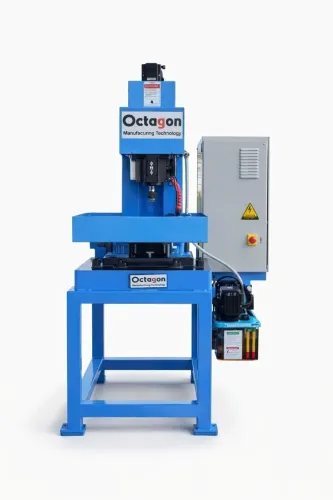
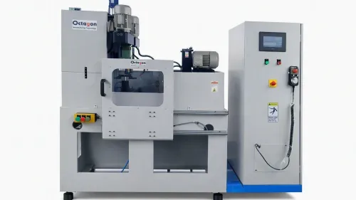
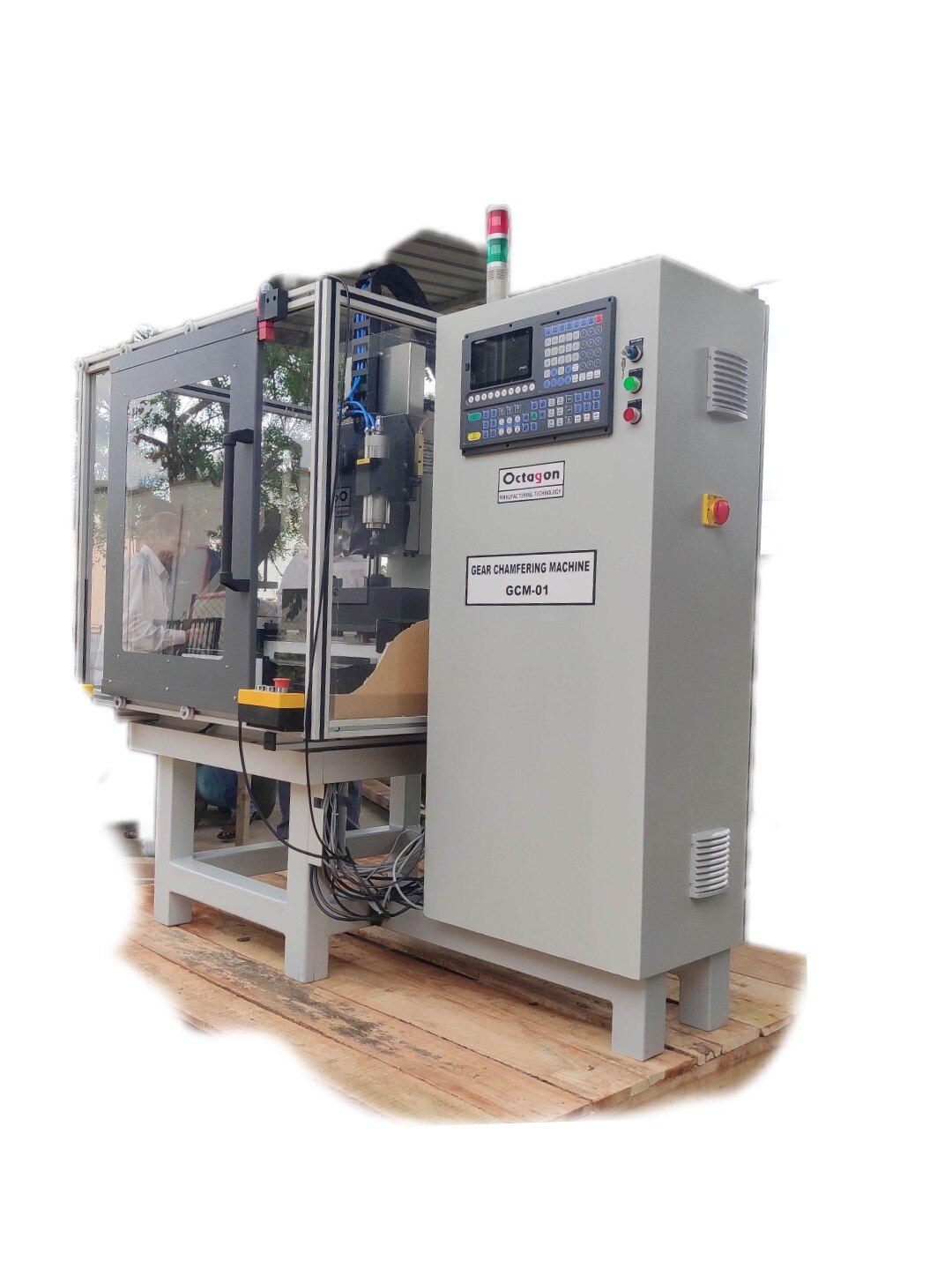
When comparing OCTAGON MANUFACTURING TECHONOLOGY with alternatives, give the automated hole drilling machine’s part mix, depth-to-diameter ratio, angular tolerances and required cycle time—not just spindle count.
Related product
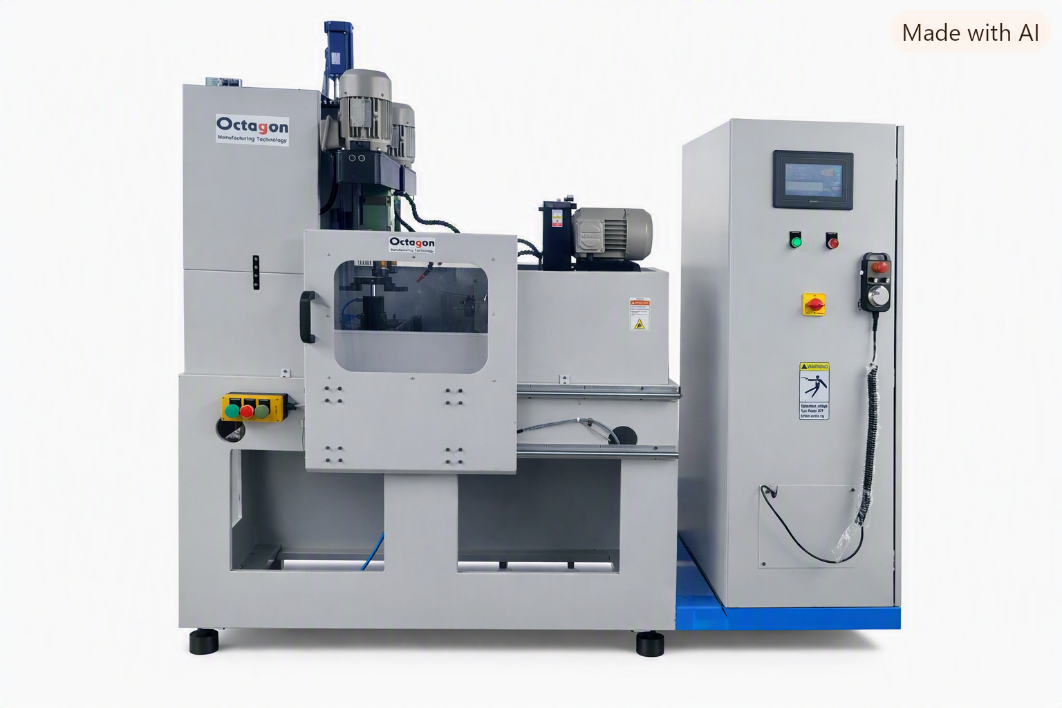 | cnc High-productivity 4-spindle CNC oil hole drilling SPM designed for accurate, repeatable and high-volume drilling operations. View product → |
Turn the application into a machine specification
Request a specification tied to the component drawing, not a label such as automated hole drilling machine. State the material and hardness, hole diameter and depth ranges, depth-to-diameter ratio, blind or through geometry, positional and angular tolerances, required cycle time, loading method, and inspection method.
| Specification item | Timing-hole requirement | Oil-hole requirement |
|---|---|---|
| Hole location | Datum-based X, Y, Z position and angular tolerance | Entry, exit and intersecting-passage coordinates |
| Workholding | Machined datums, angular chuck, indexing spindle or rotary axis | Rigid support at the drilling and breakthrough surfaces |
| Process reach | Tool length and clearance around the reference feature | Drill diameter, depth, length-to-diameter ratio and gun-drilling need |
| Quality risk | Phase error or misplaced reference hole | Burrs, chips, blocked galleries and poor cross-hole alignment |
| Utilities | Spindle speed, torque and repeatability | Coolant pressure, flow, filtration, flushing and chip evacuation |
For an oil hole drilling machine, make the supplier prove the complete passage, not only hole depth:
- Run a production-representative batch using the specified casting or forging, hardness and datum surfaces.
- Inspect hole position, angle, diameter and depth with the agreed CMM, pin gauges or bore gauges; inspect intersections and burrs visually or by borescope.
- Flush the passages, collect the chips, and record cleanliness, airflow or flow rate where the oil circuit requires it.
- Verify cycle time from load to unload, including tool changes, probing, deburring and flushing.
- Repeat the acceptance run after warm-up and tool replacement, then record repeatability and the agreed capability index.
Frequently asked questions
What is the difference between a timing hole and an oil hole?
A timing hole establishes a positional or angular reference, while an oil hole creates a passage for lubricant to reach a bearing, journal, gallery, or intersecting passage.
When does a timing hole require angular control?
Specify angular control when the hole must align with a keyway, timing mark, gear tooth, pulley feature, camshaft feature, or mating component.
What quality checks matter for an oil hole?
Check hole diameter, depth, entry and exit condition, burr removal, blockage, cleanliness, and alignment with intersecting lubricant passages.
When should you choose dedicated drilling equipment over flexible CNC equipment?
Choose dedicated equipment for repeatable high-volume work with fixed hole patterns; choose flexible CNC equipment when components, hole locations, or production requirements change frequently.