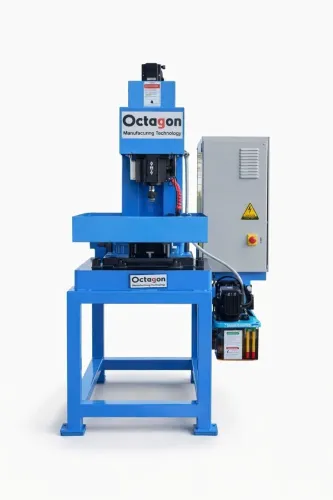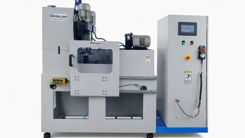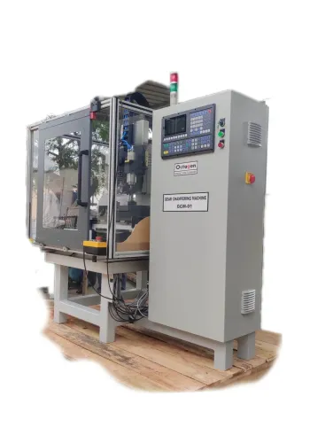

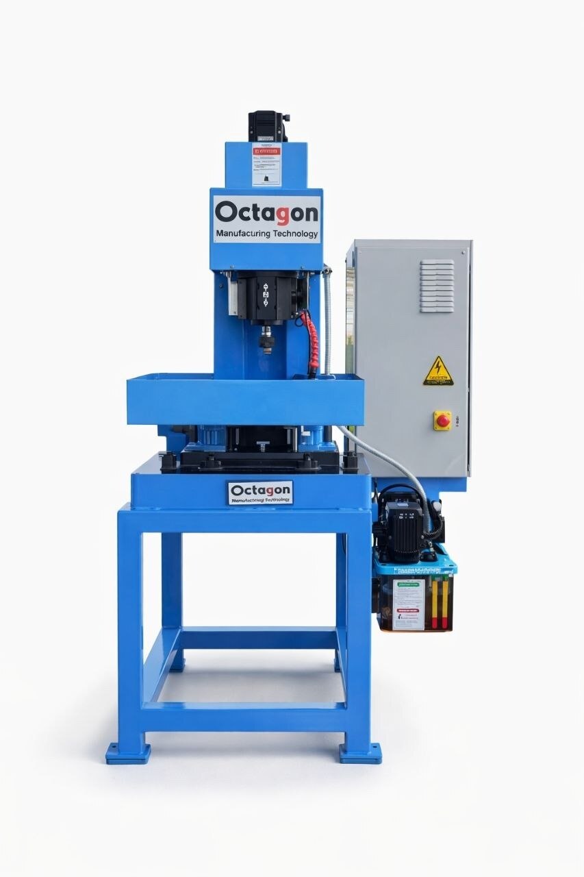
Oversized holes, drifting locations, burrs, broken drills and unexplained alarms rarely have one cause. By following a symptom-led diagnostic sequence, checking the component and fixture as carefully as the CNC, and defining acceptance evidence before purchase, you can separate machine faults from tooling, material, programming and measurement errors.
Key takeaways
- Measure diameter, position, taper, roundness, depth and burr height first.
- Track whether the defect stays with the feature or moves with the part.
- Separate fixture, tool, material and machine causes before changing offsets.
- Approve the process only after capability and repeatability checks pass.
Start with the defect, not the offset
Start by measuring the defect, not by changing the CNC offset. Confirm hole diameter, location from the component datum, taper, roundness, depth and burr height, then identify whether the error repeats on the same feature or moves with the part.
- Check datum seating, locating pins, rest pads and clamp confirmation. Dirt, casting scale or fixture deflection can shift the component.
- Check drill condition, tool projection, holder seating and spindle runout with a dial indicator.
- Prove component location with a master component or calibrated artifact. A spindle check does not prove that the datum is repeating.
- Review spindle load, coolant pressure or flow, tool-life counters, part-presence sensors and servo alarms against the defect time.
- Check chip packing, breakthrough support and coolant direction before reducing speed to control an exit burr.
- Compare measurements from cold start and after several hours. Thermal drift can move hole position or size.
Record every result in a spm drilling machine troubleshooting log. Replacing the drill after each oversized hole can hide fixture movement, runout or thermal drift while increasing tool cost.
If the defect appears only at breakthrough, inspect workpiece support, feed at breakthrough, drill-point geometry and chip evacuation. If the error grows gradually during the shift, run a warm-up cycle, stabilise coolant temperature and measure a reference feature at set intervals instead of correcting offsets after the final inspection failure.
Separate fixture, tool, material and machine causes
Separate the cause by changing one variable at a time. The search phrase spm drilling machine problems automotive components in pune often describes a process fault, not a failed machine.
1. Prove part location first. Clean the datum faces, confirm clamp pressure and part-presence signals, then load a master component or calibrated artefact repeatedly. If hole location moves with seating or clamping, inspect fixture deflection and locator wear; a spindle dial-indicator check cannot prove datum repeatability.
2. Check the tool path next. Measure drill runout at the holder, inspect point wear and margin damage, and compare every spindle in a multi-spindle head. Oversized, tapered or out-of-round holes point to runout, worn guides, poor rigidity or chatter. A single worn drill can create a partial defect pattern while other holes remain good.
3. Check material and cutting conditions. Casting scale, forging skin, hardness variation, interrupted cuts, incorrect feed at breakthrough and blocked coolant can cause burrs, short tool life, overloads or broken drills. Reducing speed alone will not cure an unsupported exit-side burr; support, point geometry, breakthrough feed and chip evacuation matter.
4. Check the machine last, using evidence. Correlate the measured defect with spindle load, coolant flow or pressure, tool-life counters, servo alarms, thermal drift and cycle interruptions. Verify axis repeatability, spindle runout and perpendicularity with a qualified artefact. Do not replace a drill after every oversized hole until fixture movement and thermal change are excluded.
Match the drilling method to the automotive component
Choose the material before choosing the drill. An SPM drilling machine for automotive components that drills aluminium cannot use the same speed, feed, point geometry and coolant recipe for cast iron or heat-treated steel.
| Material | Drilling condition to control | Common failure if ignored |
|---|---|---|
| Cast iron | Use abrasion-resistant tooling, controlled dust extraction and secure support; fine chips wear the edge. | Rapid flank wear, oversized holes and abrasive contamination |
| Aluminium | Use sharp, polished flutes, suitable rake geometry, adequate lubrication and chip evacuation. | Built-up edge, chip welding and packed flutes |
| Steel | Match feed and speed to grade and hardness; maintain coolant flow during deep holes. | Work hardening, high torque and broken drills |
| Forgings | Remove scale before cutting and allow for interrupted entry or uneven surfaces. | Edge chipping, wandering and early tool failure |
| Heat-treated parts | Verify hardness and use rigid carbide tooling or a post-heat-treatment drilling strategy. | Excessive load, poor hole location and short tool life |
Select the machine layout from the hole pattern, not the catalogue name.
- Use a single-axis SPM for holes drilled from one direction, especially when the component has one dominant datum and low-to-moderate hole count.
- Use a two-axis SPM when holes require two faces, two drilling directions or separate operations without manual repositioning.
- Use a multi-spindle SPM when many holes share a repeatable pattern and simultaneous drilling cuts cycle time. Fit each spindle with load or broken-tool monitoring; one failed drill can otherwise leave only part of the pattern defective.
Prove the hole before accepting the process
Accept the process only after the buyer’s actual component produces repeatable holes under production conditions. Use the specified datum scheme, fixture, cutting tools, coolant, incoming material and complete cycle—not an empty-machine demonstration from a cnc drilling spm in pune.
Check the evidence in this order:
- Measure diameter, depth, perpendicularity, countersink or chamfer size, surface finish, burr height and true position from the component datum. Use a calibrated CMM, bore gauge or suitable attribute gauges.
- Run a repeatability study with a master component or calibrated artifact. Separate part-location error, fixture deflection, spindle or tool runout and machine-axis error; a dial indicator on the spindle cannot prove datum repeatability.
- Test every threaded hole with thread-go/no-go gauges and record tap torque. Drilled-hole capability does not prove tap alignment, rigid-tapping synchronization or tap life.
- Leak-test oil or coolant passages at the specified pressure and time, then record pressure decay or flow loss.
- Verify fixture pressure at the cutting event, clamp confirmation before spindle start, part-presence sensing, door interlocks, emergency stop, overload response and recovery after an interrupted cycle.
| Check | Acceptance evidence | Reject if |
|---|---|---|
| Dimensional | Capability data for diameter, position, depth and finish | Any feature exceeds the drawing tolerance |
| Functional | Thread gauges, tap torque and leak-test results | Thread fails or leakage exceeds the limit |
| Safety and cycle | Interlocked clamps, alarms and a timed full cycle | The machine runs unclamped or omits loading, chip clearing, inspection or recovery |
Record spindle load, coolant flow, alarm history and tool-life counters with each defect. That record exposes drift instead of hiding fixture movement behind a replacement drill.
What to demand from a Pune SPM supplier
Require proof on your component, not a showroom cycle. Ask an spm drilling machine manufacturer in pune to run your actual part, datum scheme, tools, coolant, material condition and planned production cycle, including loading, clamping, chip clearing, inspection, tool changes and recovery after interruption.
1. Demonstrate capability for hole diameter, true position, perpendicularity, depth, burr height and surface finish. For threaded holes, include thread-go/no-go results, tap torque and rigid-tapping or floating-holder performance.
2. Demonstrate the fixture under cutting load. Monitor pneumatic or hydraulic pressure at the fixture, interlock clamp confirmation before spindle start, and show that the part cannot lift, rotate or deflect.
3. Demonstrate repeatable location with a master component or calibrated artifact. Record part-location repeatability, fixture deflection, spindle and tool runout, and machine-axis error instead of presenting a dial-indicator check alone.
4. Document the ISO 12100 risk assessment, guarding and safe recovery procedure. Inspect access to rotating spindles, automatic clamps, chip ejection, stored pneumatic or hydraulic energy, power-loss restart and broken-tool removal; verify local statutory requirements before installation.
5. Provide drawings, PLC and CNC backups, tool-life limits, alarm meanings, pressure and coolant settings, spare-parts lists, acceptance records and a fault-escalation contact. During recurring faults, require trend data that separates fixture, tool, material and machine causes.
OCTAGON MANUFACTURING TECHONOLOGY should be asked to define these evidence points before selecting between a single-axis, two-axis or multi-spindle arrangement, because extra spindles do not correct unstable datums, unsupported breakthrough or uncontrolled chip evacuation.
Related product
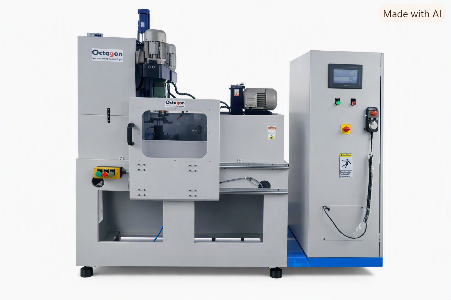 | cnc High-productivity 4-spindle CNC oil hole drilling SPM designed for accurate, repeatable and high-volume drilling operations. View product → |
Frequently asked questions
How do you troubleshoot SPM drilling machine problems on automotive components?
Measure hole diameter, location from the component datum, taper, roundness, depth and burr height. Then check whether the defect repeats on one feature or moves with the part before changing the CNC offset.
How can you separate fixture, tool, material and machine causes?
Compare parts across cavities and setups, inspect clamping and locating points, check tool wear and runout, verify material condition, and review spindle, feed and machine alignment evidence.
How do you match an SPM drilling machine to an automotive component?
Choose the drilling method from the component’s material, hole pattern, access, volume, tolerance, burr limits and required cycle time rather than selecting a machine by spindle count alone.
What proves that an automotive SPM drilling process is ready for production?
Measure trial parts against the drawing datums, confirm hole size and location, check depth, taper, roundness and burr height, and document repeatability before accepting the process.
What should you demand from an SPM drilling machine manufacturer in Pune?
Ask for a component-specific process proposal, fixture datum strategy, tool plan, cycle-time basis, inspection method, acceptance criteria and evidence from trials using your production part.