
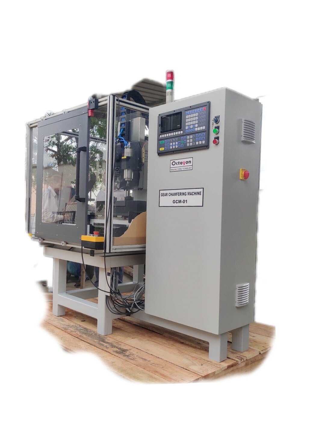
Uneven chamfers, root burrs, chatter and sudden edge damage do not always originate in the chamfering cutter. By separating cutting defects from datum, synchronization, heat-treatment and inspection errors, you can choose an edge-finishing process that protects the involute and delivers a measurable result.
Key takeaways
- Measure the same teeth before chamfering, after chamfering, and after heat treatment.
- Control tool runout, workholding, spindle alignment, and feed at the tooth edge.
- Choose brushing, thermal deburring, or CNC chamfering against burr size and edge limits.
- Validate the finished gear with defined chamfer width, angle, radius, and burr limits.
How to trace a chamfering defect to its real cause
A reliable diagnosis of cnc gear for chamfering machine problems starts by separating the defect from the stage that revealed it. Photograph and measure the same teeth before chamfering, after chamfering, and after heat treatment; otherwise a cutting burr or distortion can be blamed on the chamfering operation.
1. Inspect the unchamfered gear under magnification. A burr already present at the tooth root or flank points to hobbing, shaping, shaving, cutting direction, stock allowance, or tool exit. Check tooth thickness, profile, helix, and blank runout before altering the chamfer program.
2. Repeat the chamfer cycle after cleaning the locating bore, shoulder, and face. If the error moves when the gear is rotated or reclamped, investigate chips under the shoulder, bore runout, face runout, clamping distortion, and datum selection. A stable error on the same machine tooth points elsewhere.
3. Check the chamfering operation itself. Measure both opposing edges, inspect cutter runout and tool length, compare spindle angular synchronization, and review spindle load and chip evacuation. Gradually widening or varying chamfers across the tooth count indicate wear or a loose offset more often than a broken tool.
4. Challenge the inspection method with a calibrated optical comparator, CMM, or master gear using the same functional datum. Measure several teeth around the circumference and record chamfer width, angle, rollover, and burr height. If two methods disagree, verify probe access, gear seating, datum construction, and measurement force before changing the CNC program.
This sequence prevents a cnc gear for chamfering machine problems diagnosis from hiding a gear-cutting, workholding, or inspection error behind a new cutter offset.
Which setup variables control tooth-edge accuracy?
Chamfer width is not set by X-axis position alone. Tooth module, pressure angle, helix angle, face width and root form determine where the cutter can enter without striking a flank or running into the active involute.
Cutter tilt and path must match the specified chamfer angle; a spur gear and a helical gear require different access and synchronization logic.
| Variable | Accuracy controlled | Failure when wrong |
|---|---|---|
| Tooth geometry | Cutter access, chamfer angle and root clearance | The cutter contacts one flank or leaves burr at the root |
| Datum selection | Axial and radial position of every tooth | A trapped chip or worn locator shifts chamfer width around the gear |
| Clamping | Runout, face alignment and repeatable seating | Excess force distorts the blank; low force allows movement during cutting |
| Angular synchronization | Cutter registration to each tooth space | Chamfers vary around the circumference or enter the involute |
| Tool and spindle offsets | Actual width after wear and setup changes | One global offset hides cutter wear or fixture runout |
Use the gear bore, pilot diameter or specified locating face as the datum, then verify radial and axial runout before cutting. Clamp on a supported surface, keep chips away from the locator, and measure seating after unclamping.
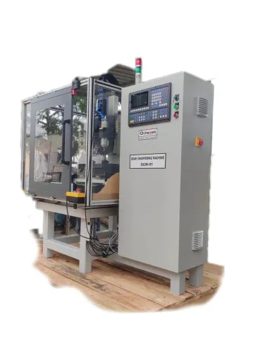
In a gear teeth chamfering machine, index the work spindle from the tooth count and phase-register the cutter to the tooth space—not merely to a machine zero. Check the first, last and several intermediate teeth; unequal results indicate synchronization, runout or access trouble rather than a simple width offset.
What a twin-spindle machine improves—and what it does not
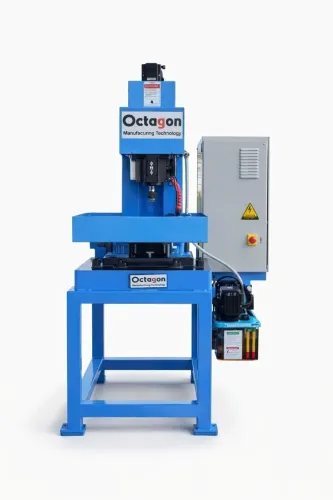
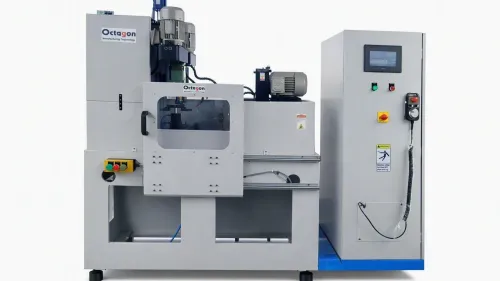
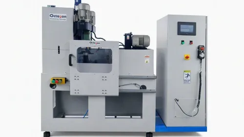
A twin-spindle CNC gear chamfering machine reduces production time when both opposing edge operations run during one loading, after one locating and clamping cycle. The gain is real only when loading, datum seating, tooth indexing, cutter approach, chip evacuation and inspection stay off the critical path; the slower spindle still sets the cycle time.
It is not automatically half.
| Condition | Time effect | What to verify |
|---|---|---|
| Both spindles cut similar chamfers simultaneously | Strongest reduction | Matching tool paths, cutting loads and approach times |
| One spindle cuts harder material or a larger chamfer | Limited reduction | The slower operation remains on the critical path |
| The gear still needs separate loading or inspection | Little reduction | Transfer, reclamping and inspection time can cancel the overlap |
Do not control both sides with one correction value. Check each spindle’s runout, tool length, cutter wear, angular synchronisation and workholding error separately; inspect the two gear faces as separate populations, not as one combined average.
Set tool-life limits by processed tooth count, record spindle-load changes and use separate wear offsets for cutter wear and fixture runout. This prevents a global offset from hiding a locating or timing fault. When comparing a twin-spindle CNC gear chamfering machine from OCTAGON MANUFACTURING TECHONOLOGY, request side-specific capability data and sample reports for both spindles.
A sound result also checks chamfer width, rollover and secondary burrs after changes to cutting direction, tooth thickness, helix angle or tool-exit position.
Related product
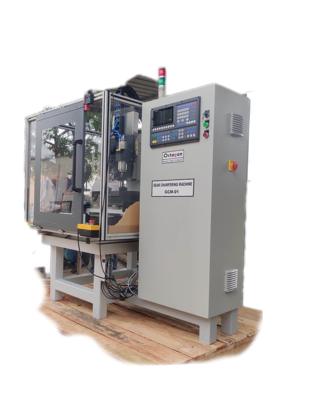 | cnc Twin-Spindle CNC Gear Teeth Chamfering Machine High-productivity twin-spindle CNC gear teeth chamfering SPM designed for high-speed, accurate and consistent chamfering of gear teeth. View product → |
Choosing between brushing, thermal deburring and CNC chamfering
Brushing suits light, flexible burr removal; thermal deburring suits burrs that project into several directions; CNC chamfering suits a specified, repeatable edge. Choose by burr formation, material hardness, tooth access and the finished edge—not by gear diameter alone.
| Option | Best match | Main limitation |
|---|---|---|
| Brushing | Small burrs across varied tooth forms, especially before heat treatment | Brush pressure, wear and dwell alter edge radius; abrasive action can smear ductile burrs |
| Thermal deburring | Fine burrs on multiple exposed edges and hard-to-reach intersections | Heat and pressure can damage thin sections, alter surfaces or leave a root condition that still needs inspection |
| CNC chamfering | Defined chamfer width, angle or radius on each tooth, including controlled root access | Requires tooth synchronisation, correct tooling and a program matched to module, helix and cutting direction |
Use a gear deburring machine when the drawing limits burr height, rollover or chamfer variation. Brushing cannot reliably replace a narrow chamfer, while thermal processing does not give the same geometric control.
Hardened gears, small tooth spaces and helical lead ends demand trials that check the involute, root and flank rather than a fingertip edge check.
A deep hole drilling machine is built for straight hole accuracy and chip evacuation through gun-drill, BTA or ejector-drill methods. It lacks the tooth synchronisation, edge-access cutters and gear-specific inspection needed for chamfering. One platform can combine both operations only after engineering shared workholding, spindle orientation, coolant delivery and cycle time.
How to specify and validate the finished gear edge
A finished edge is acceptable only when the drawing defines measurable limits, not when it merely says “deburr.” Specify maximum burr height, permissible rollover length, chamfer width with tolerance, chamfer angle or radius, root accessibility, and a no-touch zone covering the active involute and tooth tip.
1. Divide the edge into inspection zones: tooth tip, both flank lead ends, working involute, root transition, and the full face width. Set separate limits where the cutting tool exits, because a helical gear can carry a larger rollover at one lead end than the other.
2. Name the measurement method beside each limit. Use a calibrated optical comparator, microscope, vision system, or tactile profile measurement for burr height and chamfer width; use a gear-profile measurement for involute damage. A fingertip check cannot detect a root burr or a chamfer that cuts into the profile.
3. Match the process to the edge requirement. Use brushing for small, flexible burr removal when a controlled radius is acceptable; use a dedicated cutter or CNC chamfering cycle when the drawing requires a narrow, repeatable chamfer. Check root access, tooth spacing, helix angle, material hardness, and burr direction before approving the machine.
4. Validate samples after every operation that can change the edge. A pre-heat-treatment result does not prove the post-carburizing, quenching, grinding, or shot-blasting condition. Run first-off, capability, and tool-wear samples, then recheck lead ends, roots, involute protection, and chamfer size after the final operation.
Frequently asked questions
How do you trace the real cause of a gear chamfering defect?
Measure and photograph the same teeth before chamfering, after chamfering, and after heat treatment. This separates cutting burrs, chamfering errors, and heat-treatment distortion.
Which setup variables control tooth-edge accuracy?
Check tool runout, spindle alignment, workholding location, gear concentricity, tool condition, feed rate, cutting depth, and synchronization with the tooth position.
What does a twin-spindle CNC gear chamfering machine improve?
A twin-spindle machine can process opposing gear edges in one setup, reducing handling and improving process consistency. It does not correct poor workholding, inaccurate blanks, tool wear, or incorrect chamfer settings.
When should you choose brushing, thermal deburring, or CNC chamfering?
Use brushing for light, accessible burrs; thermal deburring for suitable parts with burrs in enclosed or intersecting passages; and CNC chamfering when the tooth-edge size, angle, or location requires controlled material removal.